Hydraulic cylinders for foundry technology
Die casting & low-pressure casting cylinders
Special requirements are placed on hydraulic cylinders in the die casting industry due to the ambient conditions:
- Extreme heat
- High contamination levels
- Heavy-duty continuous operation
- confined spaces
No matter what conditions a hydraulic cylinder is required to work under for you – we make it possible. With a complete system that adapts to your requirements.
Hänchen has a broad knowledge of the industry and offers you customised hydraulic cylinder for your machine.
Sales Steel and Foundry Technology
Herbert Hänchen GmbH
- Products with high dimensional accuracy
- Customised design
- Increased availability of the production plant
- On-site support
Hydraulic cylinder as guide pillar
in casting racks
The hydraulic guide pillar is an externally hardened pillar with an integrated hydraulic cylinder. This allows loads coupled to the piston rod to be precisely guided and moved without subjecting the cylinder itself to side loads.
With the hydraulic guide pillar, two functions can be achieved with one component in a space-saving manner: the linear movement of a hydraulic cylinder and the exact guide of a round pillar. Due to the hardened surface of the guide pillar, very large guide forces can be transmitted.
- Design
Single-rod cylinder with cushioning on both sides
- Equipment
Sealing system cover: Servocop®
PU/NBR for hydraulic oil up to 100°C
PU+/NBR for HFC up to 60°C
FKM for temperatures up to 200°C- Quality of piston rod
20MnV6 chrome-plated and honed
42CrMo4V hardened, chrome-plated and honed
- Mounting
Cylinder: Rectangular flange cap side,
Piston rod: Internal thread- Hydraulic ports
according to ISO 228
Port position: cap and head side or both integrated on the cap side- Guide tube
Outside: surface layer hardened 52 HRC, optionally chrome-plated
Inside: honed

|
Bore |
MM |
Stroke** | KF | AF min. |
WF | ZF** | G | MF | BD f9 |
D | BA H7 |
Y | PL | EE |
| 80 | 50 | 430 | M 30 | 35 | 28 | 729 | 28 | 50 | 130 | 129,8 | 40 | 78 | 27 | G 3/4* |
| 100 | 60 | 250 | M 36 | 45 | 30 | 615 | 114 | 55 | 155 | 154 | 40 | 119 | 32 | G 3/4 |
| 100 | 60 | 400 | M 42 x 1.5 | 60 | 28 | 835 | 105 | 70 | 160 | 155 | 50 | 110 | 40 | G 3/4 |
| 125 | 80 |
400 |
M 60 x 2 | 55 | 42 | 949 | 154 | 70 | 180 | 179,8 | 50 | 162 | 33 | G 1 |
|
Bore |
Flange |
UF | E | TF | VF | R | PF | CO -0,1 |
KF | FB | p max. |
| 80 | Type 1 | 185 | 130 | 155 | 122 | 60 | 102 | - | - | 19 | 160 bar |
| 100 | Type 1 | 225 | 155 | 150 | 190 | 64 | 118 | 25 | 5 | 21 | 200 bar |
| 100 | Type 2 | 255 | 250 | 70 | 170 | 100 | 204 | - | - | 26 | 160 bar |
| 125 | Type 2 | - | 255 | 70 | 210 | 100 | 210 | - | - | 26 | 160 bar |
Dimensions in millimetres
* EE head side additionally in the cap side flange
** Deviating stroke and installation length
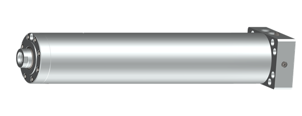
Core pull cylinders
for die casting molds
Core pull cylinders are particularly robust hydraulic cylinders that are adapted to the requirements in die casting machines.
Thanks to the externally mounted position detection system with limit switch, both end positions can be flexibly positioned to any position. The piston rod is secured against rotation by the position detection system.
A modern sealing system increases the service life of the cylinders.
- Design
Single-rod cylinder, optionally with cushioning
- Equipment
Sealing system cover: Servocop®
PU/NBR for hydraulic oil up to 100°C
PU+/NBR for HFC up to 60°C
FKM for temperatures up to 200°C- Quality of piston rod
20MnV6 chrome-plated and honed
42CrMo4V hardened, chrome-plated and honed

- Mounting
Cylinder: Quick-change flange head side
Piston rod: flanged rod end- Hydraulic ports
according to ISO 228
Port position: cap and head side- Permissible pressure
up to 160 bar
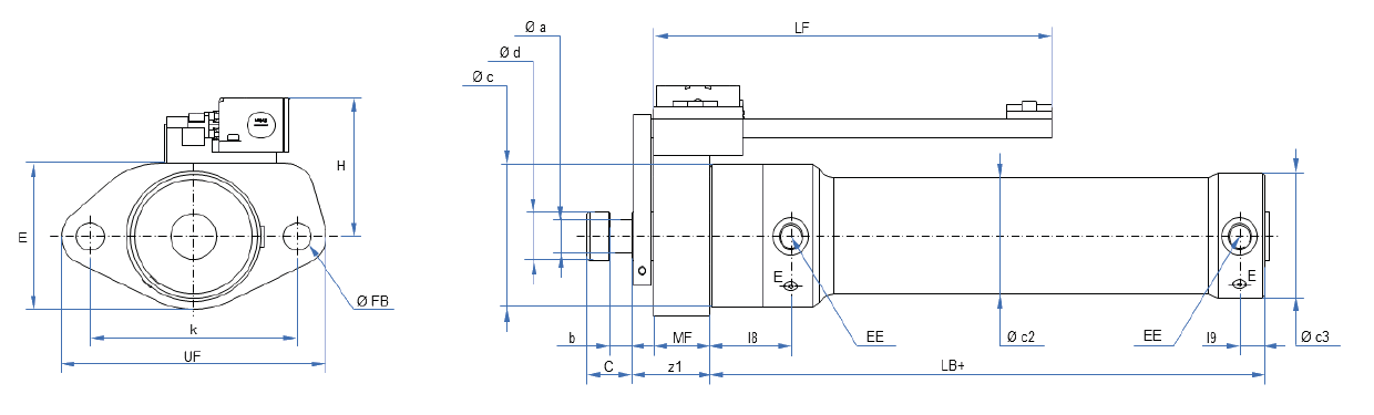
| Bore | Rod Ø |
Port | Ventilation | LB | a | d | C | b | c | c2 | c3 | l8 | l9 |
| 40 | 20 | G 1/4 | M 8 x 1 | 134 | 13 | 19 | 20 | 10 | 68 | 50 | 52 | 53 | 14 |
| 50 | 25 | G 3/8 | M 8 x 1 | 150 | 17 | 24 | 26 | 13 | 80 | 60 | 64 | 61 | 15 |
| 60 | 30 | G 1/2 | M 8 x 1 | 164 | 20 | 29 | 30 | 15 | 95 | 70 | 76 | 68 | 17 |
| 80 | 40 | G 1/2 | M 8 x 1 | 199 | 27 | 39 | 40 | 20 | 116 | 95 | 102 | 73 | 23 |
| 100 | 50 | G 3/4 | M 8 x 1 | 217 | 34 | 49 | 50 | 25 | 140 | 120 | 126 | 76 | 22 |
| 125 | 60 | G 1 | M 8 x 1 | 248 | 40 | 59 | 60 | 30 | 168 | 145 | 158 | 80 | 38 |
| 140 | 80 |
G 1 1/4 |
M 8 x 1 | 268 | 54 | 79 | 80 | 40 | 200 | 160 | 180 | 89 | 31 |
| 160 |
100 |
G 1 1/4 | M 8 x 1 | 302 | 67 | 99 | 100 | 50 | 220 | 190 | 202 | 91 | 50 |
|
160 |
120 |
G 1 1/4 | M 8 x 1 | 326 | 80 | 119 | 120 | 60 | 240 | 220 | 228 | 110 | 46,5 |
| Bore | Rod Ø |
z1 | MF | k | FB | UF | E | H | LF+ |
| 40 | 20 | 60 | 40 | 105 | 18 | 141 | 80 | 98 | 60 |
| 50 | 25 | 60 | 40 | 150 | 25 | 200 | 90 | 103 | 60 |
| 60 | 30 | 70 | 50 | 160 | 25 | 210 | 110 | 113 | 60 |
| 80 | 40 | 70 | 50 | 180 | 25 | 230 | 130 | 123 | 60 |
| 100 | 50 | 75 | 55 | 210 | 25 | 260 | 150 | 133 | 60 |
| 125 | 60 | 85 | 65 | 250 | 30 | 310 | 180 | 148 | 60 |
| 140 | 80 | 85 | 65 | 280 | 35 | 350 | 220 | 168 | 60 |
| 160 | 100 | 100 | 80 | 290 | 39 | 370 | 240 | 178 | 60 |
| 160 | 120 | 110 | 90 | 310 | 45 | 400 | 260 | 188 | 60 |
Dimensions in millimetres