
Safety catcher in machines
Safety device in mechanical engineering for vertical axles
The safety catcher is used for clamping round rods in vertical axles.
It ensures maximum safety and reliability – whether for stepless holding of loads at standstill, as a safety component for gravity-loaded axles in the event of a breakdown, or for effective fall protection in mechanical engineering.
The safety catcher locks mechanically according to a self-reinforcing principle and can be loaded either by compression or by tension. Releasing is achieved via hydraulic or pneumatic pressure.

- Safety of people and machine
- Clamping force without energy supply
- For vertical use
- Pneumatic or hydraulic
- Holding load through self-reinforcement principle
- DGUV-Test certified
Use and application of the safety catcher
The safety solution for people and machine
The safety catcher is based on our experience, grown since 1965, with clamping units in the Ratio Clamp® design. We have specifically developed this proven technology to ensure maximum safety in applications on vertical, gravity-loaded axes. This allows us to provide a higher clamping force in an emergency.
- Fixing round rods of all types, in any position
- Clamps from standstill, also for braking from movement in the event of an occasional accident
- Clamping force without energy supply for an unlimited time
- Secures axles precisely in the event of power failure, drive or control errors
- Presses & punching machines: Prevents lowering/sinking of the upper part, protects tools and operating personnel
- Machine tools: Reliably secures heavy vertical axles and spindles against falling.
- Robotics & portals: Holds tools and loads securely in position, even in the event of drive failure
- Intralogistics & lifts: Guarantees safety for people and goods in lifting systems
Functional principle of the safety catcher
The clamping unit for mechanical restraint device
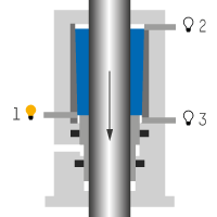
The safety catcher operates mechanically according to the friction lock principle. When unpressurised, the holding load builds up via the conical clamping system as the load falls. The self-reinforcing principle comes into effect, locking the rod in place.

Secure load
If the releasing pressure drops, the clamping segments, which are under spring preload, rest against the rod to be clamped. The resulting friction secures the load and the safety catcher is ready to take over the load.
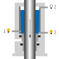
Lock, assume load
As soon as the rod to be clamped moves in the load direction, the clamping system locks in a self-reinforcing manner, whereby the clamping segments shift due to the friction up to the internal stop. This builds up the holding load and the load is assumed.

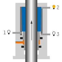
Release
The releasing pressure, whether hydraulic or pneumatic, pushes the release piston with the clamping segments upwards from the "secure load" state into the released position.
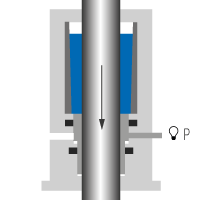
In the locked state, in addition to the releasing pressure, an external force must be applied to the clamped rod in the opposite direction to the load.Load and overload
When the load is assumed, the rod does not slip through up to the maximum permissible holding load.
An overload with the rod slipping through may occur occasionally without damaging it or the safety catcher.
Mounting the safety catcher
Mounting compressive load or tensile load


Fixed mounting flange
In addition to the centering collar permanently mounted on the safety catcher, a fixed flange can be used. When in use, make sure that the safety catcher is installed without any stress.
Loose mounting flange
In addition to the centering collar permanently mounted on the safety catcher, a loose flange can be used. This enables both radial and vertical movement compensation.

Sensors of the safety catcher
Inductive proximity switches and pressure switches
The safety catcher can optionally be equipped with up to 4 independent sensors: Depending on the required performance level of the machine into which the safety catcher is integrated, the proximity switches can be provided in a redundant version or with a diagnostic output if required.
Technical data of the safety catcher
Released by hydraulic or pneumatic pressure
In our online product configurator HäKo, you can assemble the clamping unit - safety catcher, view data sheets with detailed mounting dimensions and request the desired CAD data. Various mounting flanges and sensor technology components are available as accessories. A functional rod with freely configurable piston rod ends can also be directly mounted in the HäKo.
Technical data of the safety catcher
Released by hydraulic or pneumatic pressure
| SAFETY CATCHER FOR VERTICAL AXLES |
|||||
| + Locking + Certification |
Self-reinforcing DGUV Test |
||||
| Rod-Ø (mm) |
Permissible Load (kN) |
Installation length (mm) |
Mounting Ø |
||
| 25 | 10 | 152 | 71 | ||
| 28 | 15 | 169 | 82 | ||
| 30 | 20 | 180 | 85 | ||
| 40 | 33 | 211 | 106 | ||
| 50 | 52 | 264 | 125 | ||
| 56 | 67 | 262 | 140 | ||
| 60 | 90 | 262 | 150 | ||
| 63 | 100 | 285 | 160 | ||
| 70 | 107 | 302 | 172 | ||
| 80 | 133 | 322 | 194 | ||
The values given apply to all fluids.
Dimensions written in blue: stock sizes
The holding load of the safety catcher for machines has a safety factor of at least 2, but does not exceed a safety factor of 2.8.
- Compressive load or tensile load
- Hydraulically released: min. 40 bar, max. 250 bar
- Pneumatically released: min. 4 bar, max. 10 bar
- Factory check of the safety catcher required after 2 million switching cycles
- Max. rod speed: 0.5 m/s
- Working temperature: 0 °C to +60 °C
- Fluids: mineral oils, HFC or compressed air, others on request